Reverse Engineering

Do you have a prototype but no blueprint? Need to remake an old part that the OEM doesn’t even have a drawing for, let alone have in stock? What if your ISO 9000 system requires that you define the product you make? Are you in the aftermarket parts business? Do you have a better “mousetrap,” but can’t satisfy the requirements of the Patent Office?
If so, we offer numerous reverse engineering methods and services to define parts or products. Q-PLUS Labs provides everything from raw measurement data to (dimensioned and toleranced) parametric engineering drawings that correspond to a 3D CAD solid model. We also offer reverse engineering design consulting to point you in the right direction.
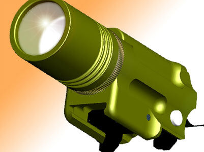
Digitizing and Scanning
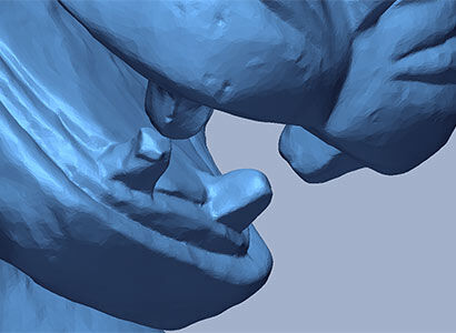
Digitizing is the method employed to digitally represent 2D and 3D shapes and objects. This is typically accomplished through the use of a laser scanning system, a white light scanning system, or a number of contact scanning systems such as a scanning CMM, an articulating arm with a hard-probe or a digital contour tracer with a stylus. The data can be recorded and/or converted in terms of points, conventional curves, splines, surfaces and solid models. This data is often used to define or analyze complex geometry, such as vane and blade profiles, and can also play a key role in comprehensive and sophisticated reverse engineering processes.
Q-PLUS Labs has vast and varied digitizing and scanning capabilities with accuracies smaller than .0001 inches and XYZ coordinate data collection at rates beyond thousands of points per second.
 |
 |
|---|
Dimensional Measurement
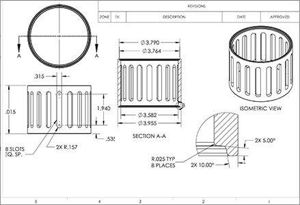
Q-PLUS Labs recognizes that many reverse engineering jobs aren’t complex and don’t require scanning at all. Further, some customers like to make their own sketches and include dimensions without values and have the values determined via dimensional measurement.
In other words, the process is almost like inspection to a drawing except the nominal values have not been predetermined and are dependent on the actual dimensional measurements themselves. But how do you obtain tolerances to use for product manufacturing? A common approach used to meet FAA and FDA requirements is to measure many known good parts basing the tolerances on detected variations.
 |
 |
|---|
3D CAD Solid Modeling
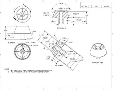
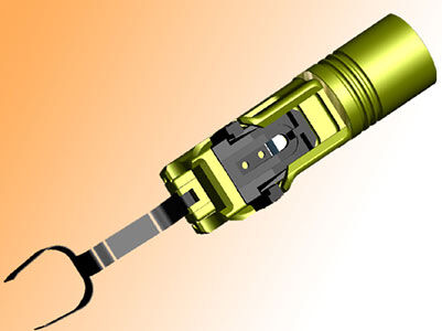
CAD Solid Modeling is the process of building a virtual three-dimensional representation of a given part, product or object. It is used for a variety of purposes such as geometry visualization, creating parametric-based drawings, reverse engineering, generating complex tool paths, programming CNC-CMMs, 3D analyses, and finite element analysis.
Q-PLUS Labs can make a parametric 3D solid model from your prototype or drawing or design one based on your specified parameters. Solid models, especially those with complex surfaces, are tested and verified to confirm accuracy requirements are met.
 |
 |
|---|
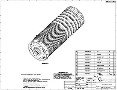
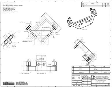
Engineering Drawings
Q-PLUS Labs provides engineering drawings that meet stringent requirements including ANSI Y14.5.
The drawings can be generated from parametric 3D solid models, also created by Q-PLUS Labs, or from a model you provide in a variety of formats, including .STP and .IGS. We can also convert old paper drawings to CAD format for advanced quality control and easier maintenance.
 |
 |
|---|